Overview
HornetX is the training program before having a chance to join NUS Bumblebee’s core team, where we build an Autonomous Underwater Vehicle (AUV) from scratch with limited budget and time.
This was my attempt to produce near-industrial grade RPY (Roll, Pitch, Yaw) estimates from cheap hobby IMUs, which was LIS3MDL (magnetometer) + MPU6050 (gyroscope + accelerometer), using proper calibration techniques, and writing my own sensor fusion algorithm.
Highlights
- Sensor fusion experiments (“quaternions” + Kalman).
- Calibration, frame alignment, and debugging.
- Do give my blog post a read on how I tackled Coupling Effects.
The end product
View my code on Hornet X Repository here on Github
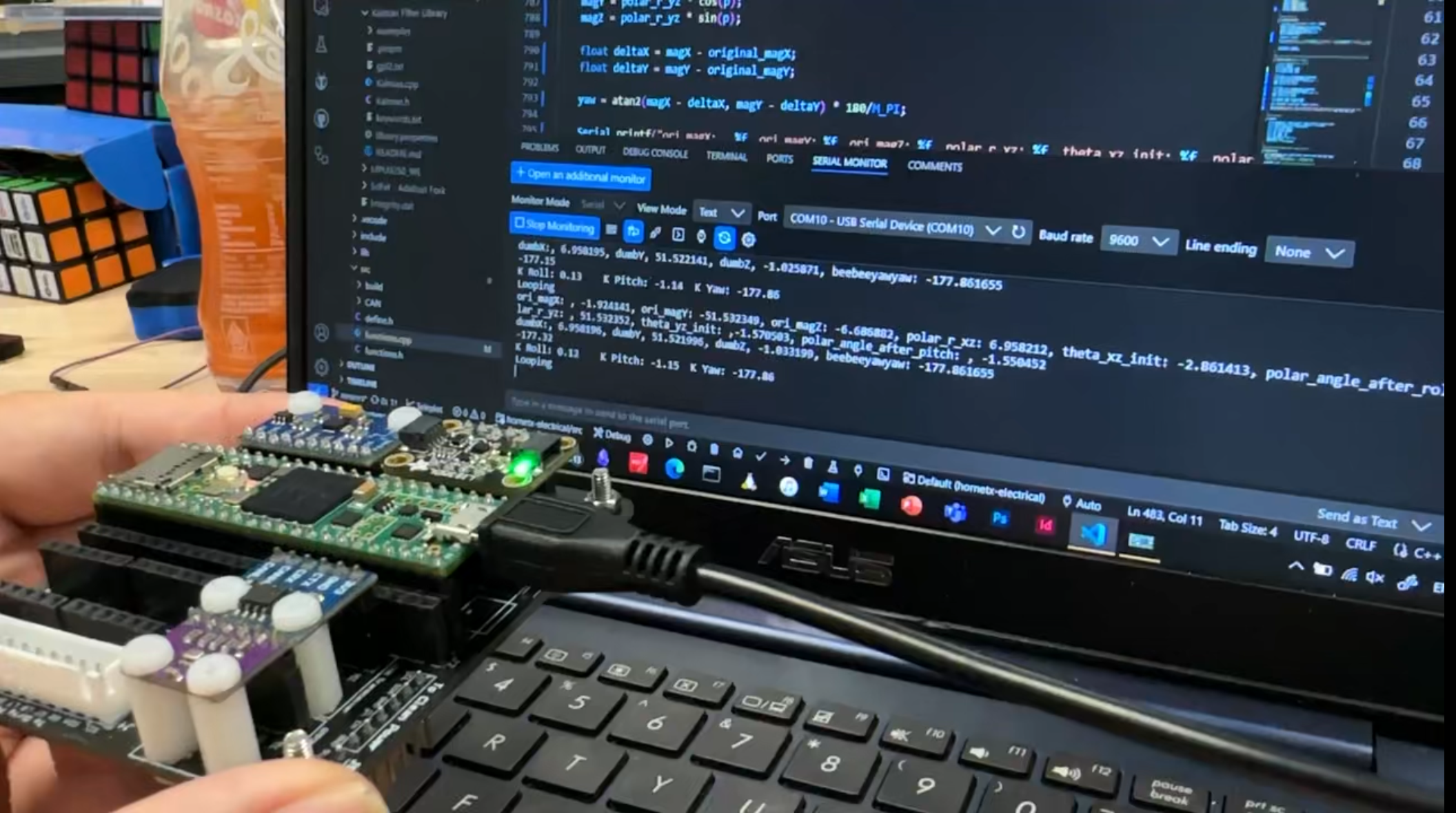
Below is an extraction of the core algorithm used to compute corrected yaw from raw magnetometer readings, compensating for roll and pitch.
void getCorrectedYaw(float r, float p)
{
	// convert roll and pitch to radians
	r *= M_PI / 180.0f;
	p *= M_PI / 180.0f;
	float original_magX = magX;
	float original_magY = magY;
	float original_magZ = magZ;

	//for roll
	float polar_r_xz = sqrt(magX*magX + magZ*magZ);
	float theta_xz_init = atan2(magX,magZ);
	float polar_angle_after_roll = theta_xz_init - r;
	magX = polar_r_xz * cos(r);
	magZ = polar_r_xz * sin(r);

	//for pitch
	float polar_r_yz = sqrt(magY*magY + magZ*magZ);
	float theta_yz_init = atan2(magY,magZ);
	float polar_angle_after_pitch = theta_yz_init - p;
	magY = polar_r_yz * cos(p);
	magZ = polar_r_yz * sin(p);

	float deltaX = magX - original_magX;
	float deltaY = magY - original_magY;

	yaw = atan2(magX - deltaX, magY - deltaY) * 180/M_PI;
}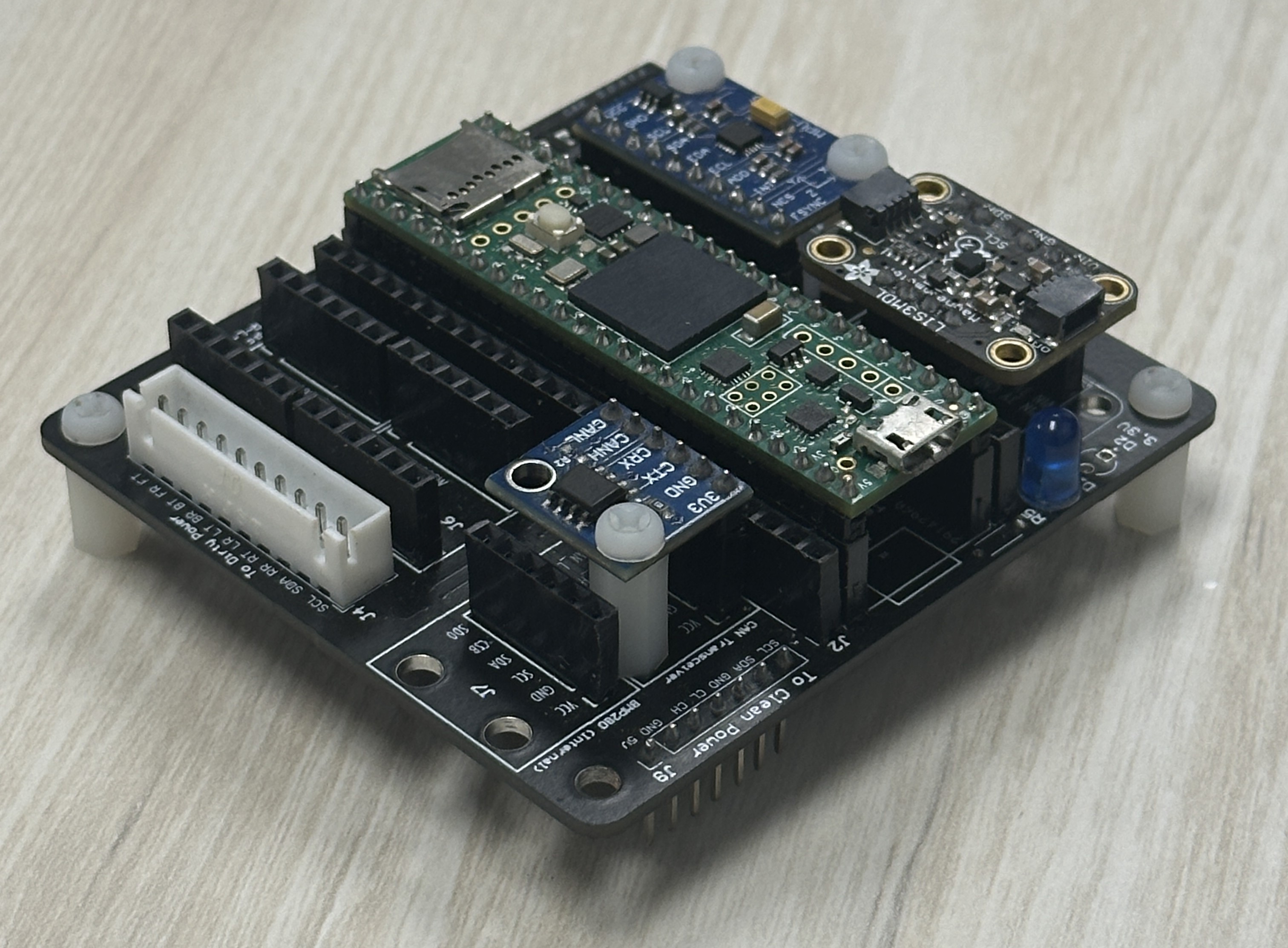
Custom sensor PCB for Hornet X.
The process
The problem: yaw changes when I only roll/pitch
Roll and pitch estimates were stable and accurate (no obvious drift), but yaw would change whenever the board is rolled or pitched, even when it was not rotated about the vertical axis.
This turned out to be expected behaviour for a naïve compass heading: using yaw = atan2(magX, magY) only works when the sensor is close to level. The magnetometer measures the Earth’s magnetic field as a 3D vector in the sensor (body) frame. When the board tilts, the horizontal projection of that vector changes in body coordinates, so the “flat” heading changes unless you properly tilt-compensate the magnetometer.
—
Investigation notes
When debugging this issue, I observed several patterns:
- Mag calibration and interference checks
- I re-did calibration outdoors to reduce environmental interference.
- The direction of the measured field generally made sense, but when pointing each axis toward magnetic north the magnitudes were inconsistent.
- That mismatch is a common sign of soft-iron distortion / axis scaling / misalignment (not just hard-iron offsets). In other words: even with good offsets, the sensor can still read an ellipsoid instead of a sphere.
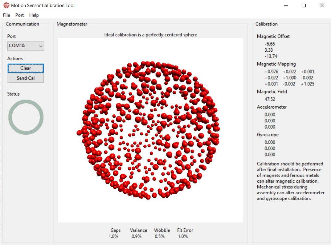
Using Magcal to calibrate magnetometer readings to a sphere.
- Tilt compensation using accel was too noisy
- An early approach used accelerometer-derived “gravity direction” to remove tilt from the magnetometer.
- In practice,
âwas noisy whenever there was vibration / motion, which caused yaw jitter or incorrect compensation. - Switching to the AHRS’ estimated gravity direction (e.g. Madgwick “gravity” vector derived from the current orientation) made the compensation much more stable because it is implicitly gyro-smoothed.
- Sign conventions and quadrant issues
- A hand-derived roll/pitch correction using trig worked for some directions (e.g. positive roll/pitch), but failed in other quadrants.
- The failures were mostly due to frame convention mismatches (sensor axes vs math axes) and inconsistent signs in
atan2()usage.
- Filtering can’t fix a wrong measurement model
- Trying to “filter the yaw harder” (Kalman/Madgwick parameters, Q/R tuning) did not solve the core issue.
- If the yaw measurement is wrong under tilt, a filter will only smooth the wrong measurement.
The fix: rotate magnetometer into a level/world frame, then compute yaw
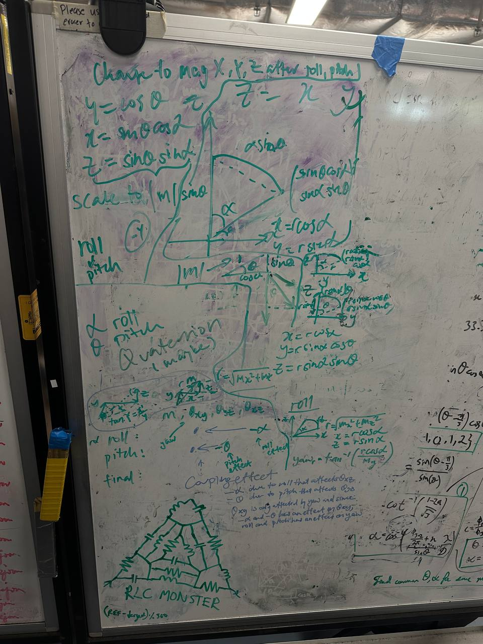
The whiteboard (my favourite tool!) where I derived the quaternion-based tilt compensation method.
The robust pattern is:
- Use an orientation estimate (quaternion) from a fusion filter.
- Use that orientation to rotate the magnetometer vector into a stable reference frame (or equivalently, remove roll/pitch from the mag).
- Compute yaw from the leveled horizontal components.
Derivation notes
To solve coupling effect
- after working on the trigonometry of 2 planes of roll and pitch to see how x y and z changes, and using polar coordinates to represent tilt and resultant coordinates, we somehow came to the concept of quaternions. The gist is that there are 3 variables as shown in the table: theta_xz, theta_yz, theta_xy. First one changes with roll, since we rotate about y, which will change magX and MagZ. Similarly for theta_yz it changes with pitch, since we rotate about x, which will change magY and magZ. yaw is computed by atan2(magX, magY). As we see, roll or pitch changes magX and magY. So even if we don’t yaw, if magX and magY changes from roll and pitch, yaw will change when it shouldn’t. So the solution is to offset the change in both X and Y when we roll and pitch, so that it does not affect yaw. Note that X and Y should still change as they should.
Then for 90 degrees test We do a regression line by taking values of each pitch and plot the yaw, to get a corrective function
Concretely, if you have the AHRS quaternion q describing body → world, then rotate the body-frame magnetometer vector m_body = [mx, my, mz] into world frame:
m_world = q ⊗ m_body ⊗ conj(q)
yaw = atan2(m_world.y, m_world.x)
This avoids the “coupling effect” where roll/pitch changes the apparent magX/magY used by atan2().
In my implementation, I also kept a small amount of empirical correction for edge cases (e.g., near-vertical orientations and residual distortion) and validated using repeatable tilt tests (e.g., a 90° pitch/roll sweep) to confirm yaw remains consistent.
Conclusion
Unknowingly, I had stumbled upon the concept of quarternions, which is in fact widely used to report a 3D body’s orientations.
By going back to the whiteboard and deriving the equations from first principles, I was able to understand why quarternions are used so widely in 3D orientation problems, and how they can be applied to solve the coupling effect problem in yaw estimation.
Now, I can conclusively say that hobby sensors are not as bad as they seem, if you know how to properly calibrate and process their data!