Introduction
In this IoT RTOS project, the FRDM board runs FreeRTOS alarm logic and actuator control, while the ESP32 provides the Wi-Fi web UI and IMU-based tilt detection.
This is the final project for CG2271 Real-Time Operating Systems. The course introduces students to bare-metal programming on the FRDM-MCXC444, and how to combine it with FreeRTOS.
The project involves developing a FreeRTOS-based Internet of Things (IoT) system from scratch using a set of hobby sensors, LEDs or motors as actuators, and a dual-MCU architecture: an FRDM-MCXC444 as the main RTOS controller, and an ESP32-S2-DevKitM-1 for Wi-Fi and web UI.
The evaluation focuses on FreeRTOS coordination between ISRs and task design, correct use of semaphores and queues, implementing both polling and interrupt-driven sensors, and integrating an ESP32.
Project Idea Formulation
While project ideas are open-ended, many teams decided to build plant monitoring systems, using soil moisture sensors and ultrasonic sensors. I wanted to create something different and challenging.
At the time, I was also working on my object tracker FPGA project for EE2026, but I still wanted to build an IoT system that felt relevant and practical, rather than a project “just to tick the box”.
Final Product Demo and Overview
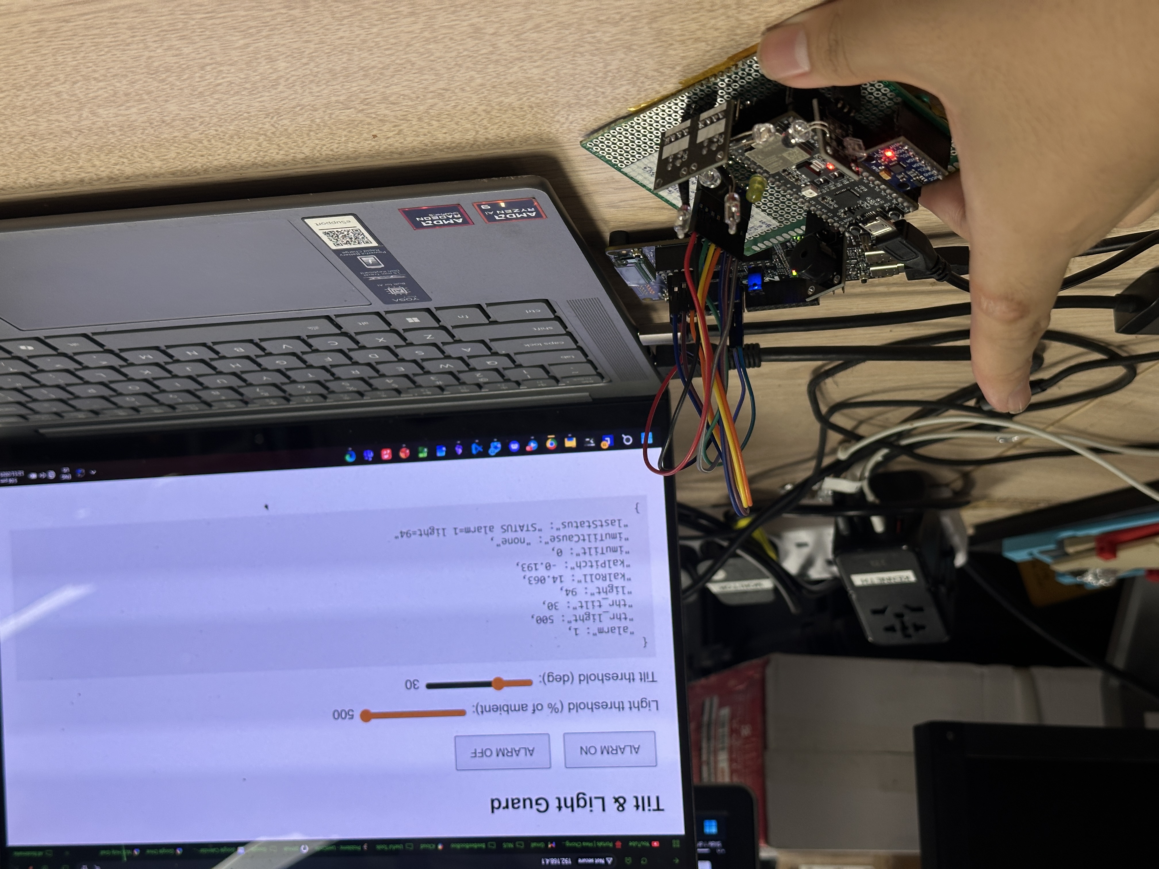
Final product: IoT Tilt & IR Security Device with web UI for remote monitoring
SecurityGuard is an embedded two-board system that detects device tilt and changes in infra-red (IR) light level, and triggers an audible and visual alarm. It cleanly separates responsibilities:
ESP32-S2: Wi-Fi access point, web UI, IMU (MPU-6050) integration, Kalman filtering, tilt threshold comparison, and transmission of compact tilt status (
IMU_TILT=0|1) and user commands from web UI (ALARM_ON,ALARM_OFF,TH_LIGHT) to the FRDM board over UART.
FRDM-MCXC444: Multi-task FreeRTOS design using semaphores, queues, pre-emption, and time-slicing to coordinate actuator control (buzzer via PWM, LED brightness via PWM), ADC sampling of the IR sensor, GPIO interrupt-driven tilt switch input, alarm state management, and periodic status reporting (
STATUS alarm=X light=Y).
Board-to-board communication is achieved through a bidirectional ASCII UART protocol for commands, status, and telemetry (ALARM_ON, ALARM_OFF, TH_LIGHT=NNN, IMU_TILT=0|1, STATUS alarm=X light=Y). The ESP32 hosts an embedded web server and UI (single HTML page) for threshold adjustment, alarm control, and telemetry, using Wi-Fi AP mode and JSON.
The entire product is packaged neatly into a single unit on a protoboard, using a single row of 8 DuPont wires to connect to the FRDM-MCXC444 board. Connect to the SSID TiltGuard Wi-Fi network and enter the IP address 192.168.4.1 in any web browser to access the web UI.
Software Architecture
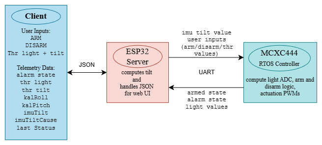
Dual-MCU with UART message passing, FreeRTOS on FRDM and ESP32 web server
Using tasks, ISRs, semaphores, queues, time-slicing, and pre-emption, the architecture ensures alarm arm/disarm (including manual disarm via the tilt switch) takes effect without delay. FreeRTOS on the Cortex-M0+ is pre-emptive, so the controller task (priority 4) can interrupt the tone tasks (priority 2) immediately when semaphores are given. The equal-priority tasks (priority 3: UART RX/TX, ADC, LED) rely on yielding and explicit time-slicing (via xQueueReceive, xSemaphoreTake, and vTaskDelay), which keeps I/O and sensing responsive.
Conceptually, external events (web commands, IR threshold crossings, IMU tilt status, and the physical tilt switch) are translated into queue messages or semaphores that the controller task uses to update the alarm state immediately.
1. Tasks Architecture
As the actuators and sensors are distinct, I follow the general rule of assigning each to its own task.
  xTaskCreate(stateControllerTask, "controller", configMINIMAL_STACK_SIZE+100, NULL, 4,NULL);
  xTaskCreate(recvTask, "uart_recv", configMINIMAL_STACK_SIZE+120, NULL, 3, NULL);
  xTaskCreate(sendTask, "uart_send", configMINIMAL_STACK_SIZE+120, NULL, 3, NULL);
  xTaskCreate(playHappyTuneTask, "task_happy", configMINIMAL_STACK_SIZE+100, NULL, 2, &taskHappyHandle);
  xTaskCreate(playPoliceSirenTask, "task_alert", configMINIMAL_STACK_SIZE+100, NULL, 2, &taskAlarmHandle);
  xTaskCreate(convertADCTask, "task_adc", configMINIMAL_STACK_SIZE+100, NULL, 3, NULL);
  xTaskCreate(setPWMTask, "task_ledpwm", configMINIMAL_STACK_SIZE+100, NULL, 3, NULL);

vTaskStartScheduler();- Overall program and state control:
stateControllerTaskowns alarm state transitions and controls the sharedcurrentStateandstopFlag. (Highest priority: 4) - Communication tasks:
recvTaskandsendTaskhandle UART protocol parsing and status transmission without blocking higher-priority control. (Priority: 3) - IR sensor pipeline:
convertADCTaskperforms ADC polling and pushes IR values intodataQueue.setPWMTaskconsumes queue entries and drives LED PWM. This separation decouples sampling timing from actuator timing. (Priority: 3) - Actuator tone generation:
playHappyTuneTaskandplayPoliceSirenTaskproduce melody/siren patterns when armed/alarming, but are intentionally lower priority so they yield immediately when the system state changes. (Priority: 2)
The creation lines in main() show explicit priority layering: controller (4) > comms & sensor (3) > audio (2). This ensures a newly signalled alarm ON/OFF transition pre-empts any ongoing tone or peripheral activity.
2. ISRs and UART
Two ISRs exemplify the “do the minimum, then defer” principle: they avoid blocking calls and slow functions to reduce the risk of delaying important tasks. Both use BaseType_t hpw and portYIELD_FROM_ISR to trigger an immediate context switch if a higher-priority task (the controller) is unblocked.
-
UART2 is used between MCUs as it is more versatile. Data is transmitted using interrupts handled by
UART2_FLEXIO_IRQHandler: it only (a) advances a TX pointer (or disables TX when finished), (b) appends RX bytes into a staticrecv_buffer, and (c) on newline, detects a complete line and callsxQueueSendFromISR(queue, …, &hpw); portYIELD_FROM_ISR(hpw);. Protocol parsing (e.g.,ALARM_ON) is done inrecvTask, not inside the ISR, avoiding variable-length string operations in interrupt context. -
PORTC_PORTD_IRQHandler: it reads the tilt switch flag, snapshotscurrentState.isAlarminginside a brief critical section, and conditionally issuesxSemaphoreGiveFromISR(disarm_signal, &hpw); portYIELD_FROM_ISR(hpw);. It does not attempt to stop PWM or manipulate tune tasks directly; it simply signals intent quickly and defers the work to tasks.
3. Binary Semaphores
Binary semaphores are used for state-change requests: alarm_signal (ON) and disarm_signal (OFF).
stateControllerTask takes semaphore:
    if (!alarming) {
      // Alarm is currently OFF: watch for any ON request
      if (xSemaphoreTake(alarm_signal, pdMS_TO_TICKS(5)) == pdTRUE) {
        taskENTER_CRITICAL();
        currentState.isAlarming = 1;
        currentState.isArmed = 0;
        stopFlag = 1; // interrupt any ongoing tune immediately
        taskEXIT_CRITICAL();

        // Nudge both tone tasks so they can switch promptly
        xTaskNotify(taskHappyHandle, 0, eNoAction);
        xTaskNotify(taskAlarmHandle, 0, eNoAction);
      }
    } else {
      // Alarm is currently ON: watch for any OFF request
      if (xSemaphoreTake(disarm_signal, pdMS_TO_TICKS(5)) == pdTRUE) {
        taskENTER_CRITICAL();
        currentState.isAlarming = 0;
        currentState.isArmed = 1;
        stopFlag = 1; // interrupt siren immediately
        taskEXIT_CRITICAL();

        xTaskNotify(taskHappyHandle, 0, eNoAction);
        xTaskNotify(taskAlarmHandle, 0, eNoAction);
      }
}- Alarm activation uses
alarm_signal = xSemaphoreCreateBinary();, and deactivation usesdisarm_signal = xSemaphoreCreateBinary();. - Give:
recvTasktranslates incoming command lines (e.g.,ALARM_ON), andconvertADCTaskgivesalarm_signalwhen the IR threshold is crossed.PORTC_PORTD_IRQHandlergivesdisarm_signalwhen physical tilt indicates a disarm action. xTaskNotify: task notifications allow fast interruption of long-running tone loops.
4. Queues
Queues decouple producer and consumer timing.
static void recvTask(void *p) {
  while(1) {
    TMessage msg;
    if(xQueueReceive(queue, (TMessage *) &msg, portMAX_DELAY) == pdTRUE) {
      // Trim CRLF
      char *line = msg.message;
      size_t n = strlen(line);
      while (n && (line[n-1] == '\r' || line[n-1] == '\n')) { line[--n] = '\0'; }

      if (strncmp(line, "ALARM_ON", 8) == 0) {
        // Turn alarm ON
        xSemaphoreGive(alarm_signal);
      } else if (strncmp(line, "ALARM_OFF", 9) == 0) {
        // Turn alarm OFF
        xSemaphoreGive(disarm_signal);
      } else if (strncmp(line, "TH_LIGHT=", 9) == 0) {
        // Set LDR threshold
        const char *pnum = line + 9; unsigned val = 0;
        while (*pnum >= '0' && *pnum <= '9') { val = val*10 + (unsigned)(*pnum - '0'); pnum++; }
        ADC_THRESHOLD = (uint16_t)val;
      } else if (strncmp(line, "IMU_TILT=", 9) == 0) {
        int tilt = (line[9] == '1') ? 1 : 0;
        if (tilt) {
          xSemaphoreGive(alarm_signal); // IMU tilt triggers alarm ON
        }
      }
    }
  }
}- queue = xQueueCreate(QLEN, sizeof(TMessage)); for UART RX lines. ISR pushes complete lines; recvTask blocks in xQueueReceive(…, portMAX_DELAY) until a line arrives, then parses. This eliminates partial line concurrency hazards.
- dataQueue = xQueueCreate(10, sizeof(uint16_t)); links convertADCTask (producer) and setPWMTask (consumer), used for IR sensor pipeline (as explained above).
Hardware Architecture
TODO : insert schematic diagram here
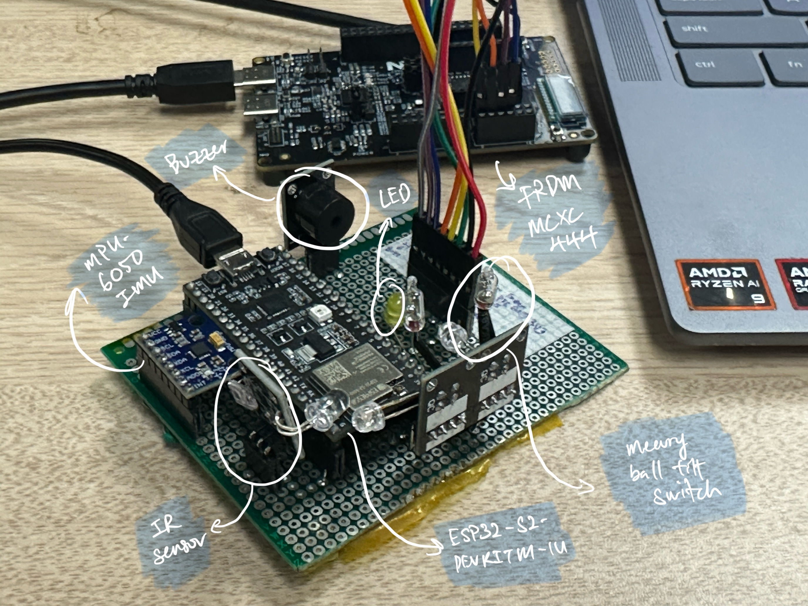
Final product protoboard layout
1. MPU-6050 IMU for tilt detection
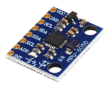
MPU-6050
Interfacing on ESP32:
Uses I2C protocol (SDA to pin35 and SCL to pin33 of ESP32 GPIO) to poll for data. The IMU provides raw accelerometer (ax, ay, az) and gyroscope data (gx, gy, gz), which are sampled on ESP32 in a periodic task. Tilt is measured on two axes:
A Kalman filter fuses gx, gy, gz with the computed roll and pitch to reduce drift over time (done on the ESP32). The IMU tilt decision is derived from the Kalman outputs using a user-set threshold (thr), and is reported to the MCXC444 every 250 ms.
Why Kalman filter?
Application of Kalman filter on IMU Readings on the ESP32
Hobby sensors such as the MPU-6050 are prone to measurement error. The gyroscope provides smooth angular-rate readings, but it suffers from drift. The accelerometer does not drift, but its measurements are noisy and easily disturbed by vibration. Kalman filter is a probabilistic tool that fuses multiple potentially noisy sources of data to infer the true value of a state. In this application, gyroscope and accelerometer data are combined to estimate roll and pitch angles, done in two stages. The Predict/Estimate step integrates gyro readings over a time interval (dt) to produce a predicted orientation that is smooth but uncertain due to drift and then the Update/Correction step takes the current accelerometer reading and depending on Kalman gain (relative confidence in each sensor), fuses to produce a current angle reading with higher accuracy.
This sensor caught my eye.
This is most probably the most challenging sensor to use out of the 45 given. Proper interfacing with it requires I2C and sensor fusion which is beyond most students (My implementation can be found in my Github repository.)
However, I have been using this in my FALCON, teleoperated robot and Hornet X projects, leading to me being the only one to use it.
2. IR Receiver for human detection
IR Receiver
Uses PTE20 (ADC0_SE0) and is sampled on the FRDM board by an ADC task; values are mapped to 0–100% of ambient IR and sent to a queue for the LED PWM task; an IR value below the threshold triggers an alarm semaphore.
Polling: convertADCTask uses readADC(ADC_CHANNEL) – busy-waits until completion and pushes the sample into dataQueue. This task runs every vTaskDelay(pdMS_TO_TICKS(10)).
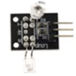
3. Tilt Switch for manual disarm
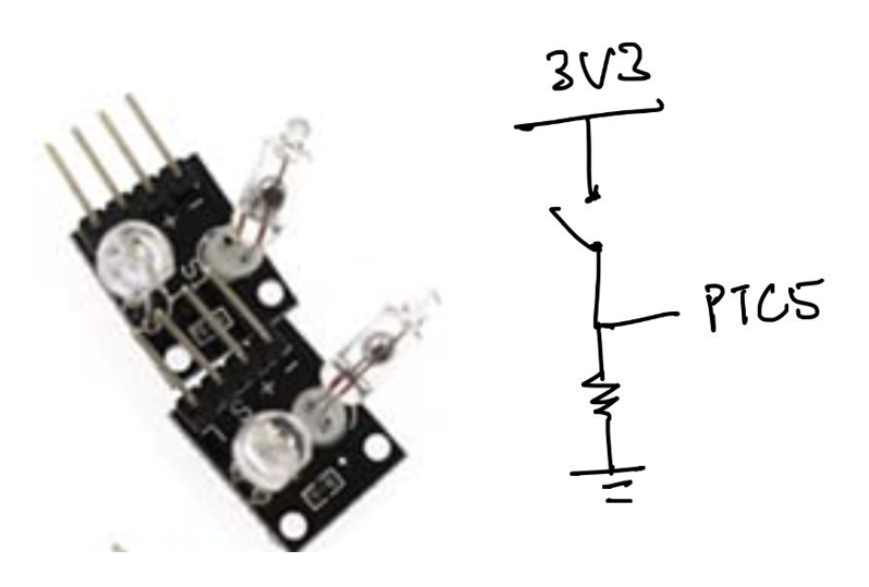
Mercury Tilt Switch
Wired to PTC5 (GPIO interrupt). The switch is normally closed. When the switch is tilted, the mercury ball rolls and opens the switch, triggering an ISR on the falling edge that posts a semaphore for a disarm request when the system is alarming. This provides a simple physical “acknowledge/reset” input while still deferring work to tasks (no slow/blocking calls in the ISR).
4. Buzzer and LED for alarm actuation
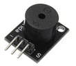
Passive Buzzer
Driven by a TPM PWM signal on PTE29 (TPM0_CH2) to play different tones. The buzzer uses a centre-aligned PWM configuration on TPM0_CH2. Frequency control is set by recomputing MOD and CnV.
If the alarm state is false, the buzzer plays a melody (playHappyTuneTask()) until an event is triggered by overtilt, overIR, or the web button; it then plays a siren (playPoliceSirenTask()) until a reset by the tilt switch or web button.
Both comprise a sequence of playToneInterruptible() calls that check stopFlag, so they can exit immediately when a state-change event occurs.
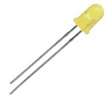
Standard LED
The LED is driven by TPM PWM signal on PTE21 (TPM1_CH1). The LED actuator is updated from the ADC queue consumer. This causes the LED’s brightness to be proportional to adcValue (i.e. IR received by IR sensor) in real time.
Soldering into a complete product
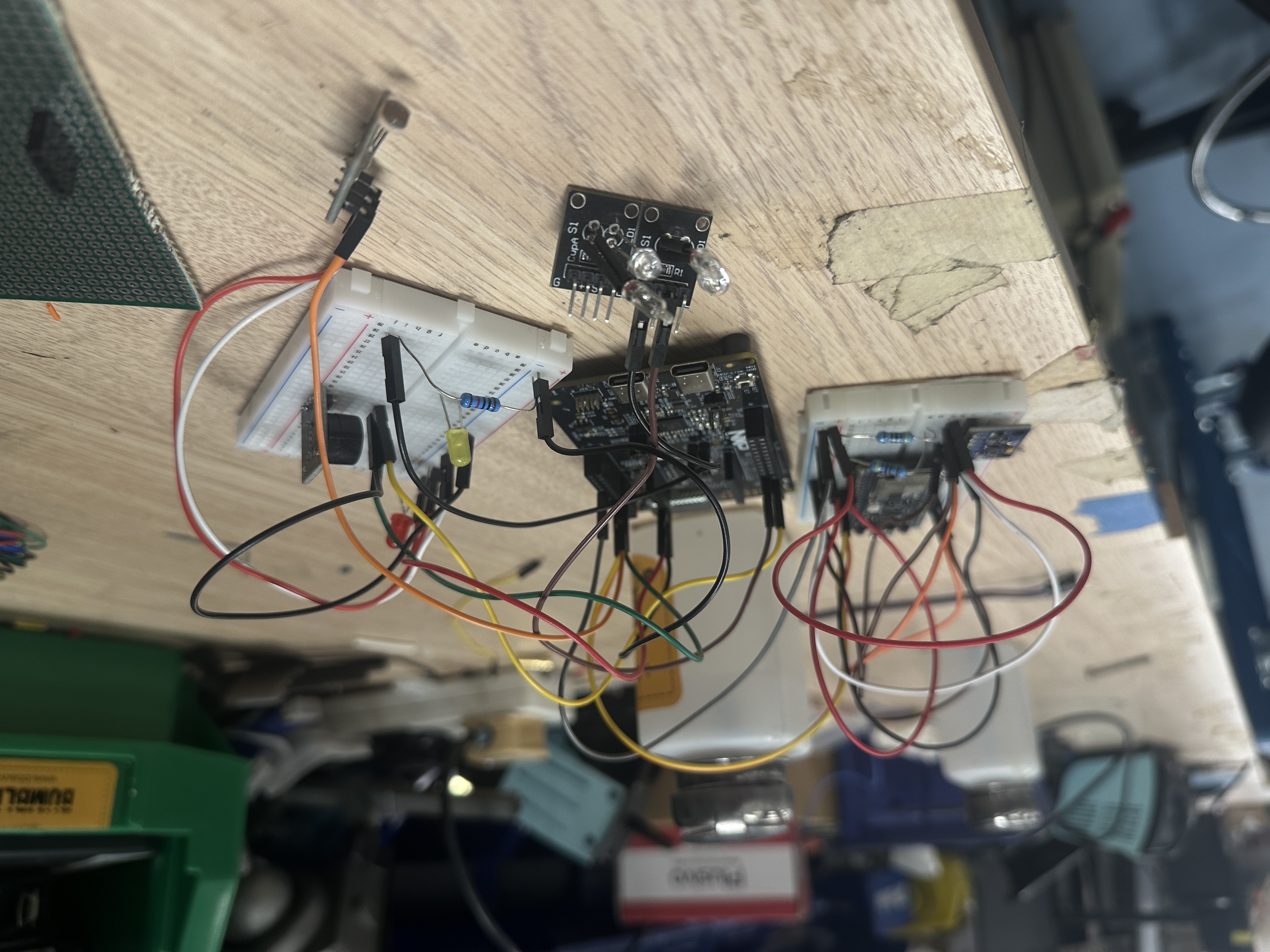
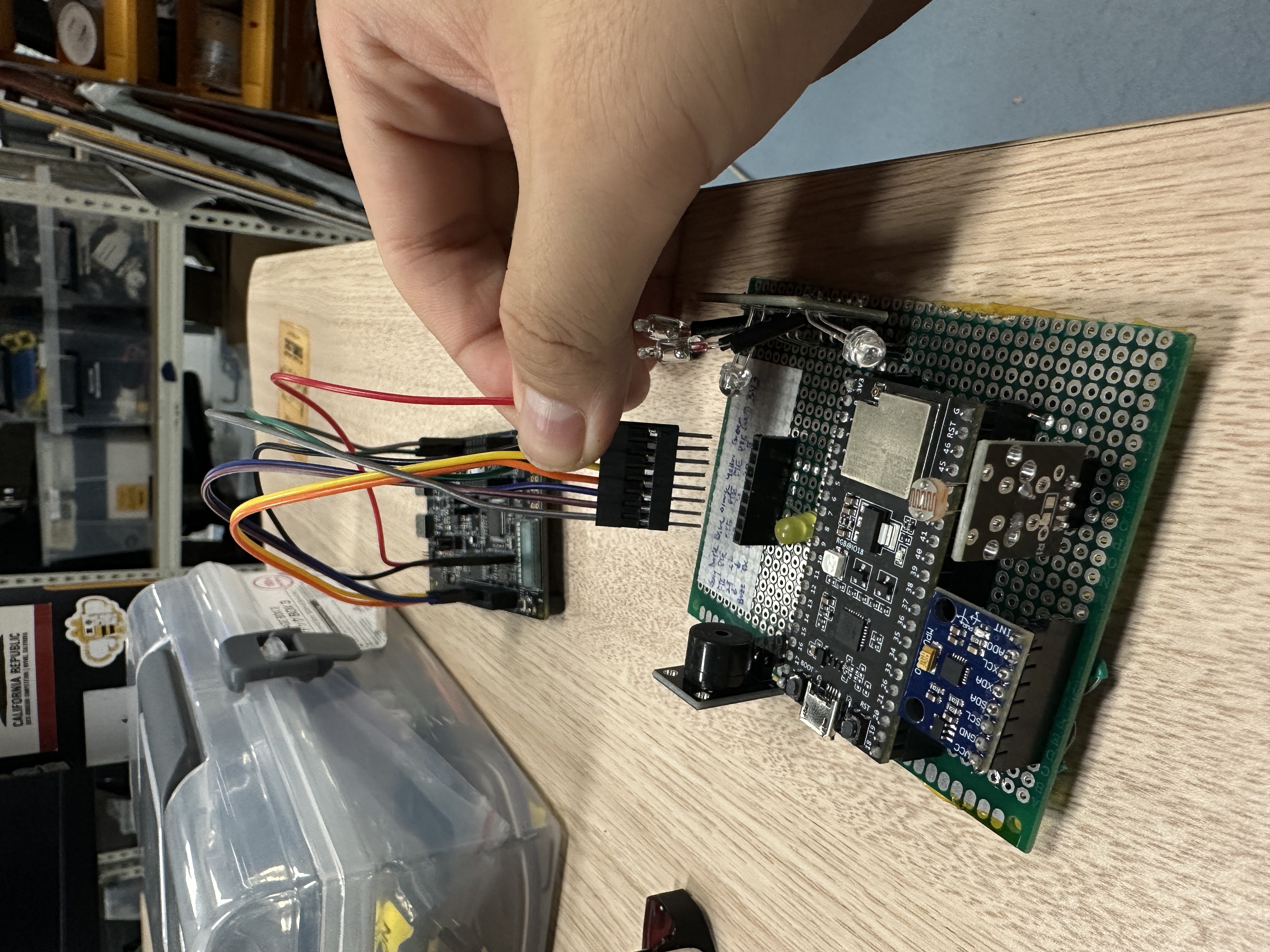
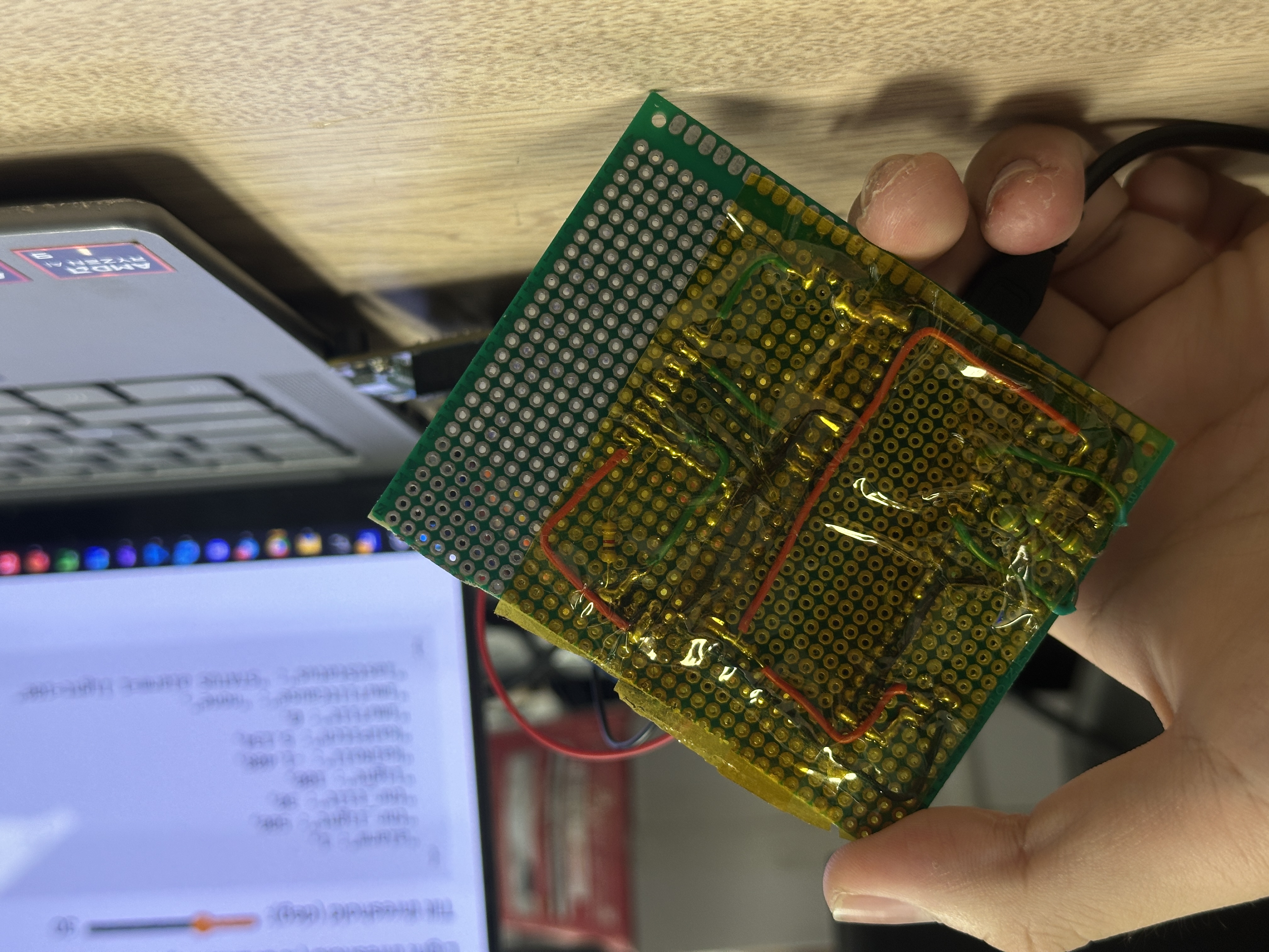
Instead of two breadboards with multiple jumpers dangling everywhere, all modules were soldered onto a protoboard as an integrated product for robust electrical connections (leaving only 8 jumpers to the FRDM board). This is particularly important for communication signal integrity (I2C and UART), and it reduces intermittent resets while significantly improving debugging reliability.
It is surprising (to me at least) that everyone used breadboards for their final products, which are prone to loose connections, especially for a dual-MCU product with many connections.
ESP32 Web Server and UI
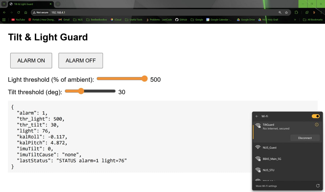
Web UI
The ESP32 hosts a lightweight HTTP server with a simple web UI that sends commands (alarm on/off, set thresholds) and fetches status via JSON. Telemetry is updated at 2 Hz, including data from the FRDM board. The HTML page is embedded in the ESP32’s PROGMEM. Simply connect to the SSID TiltGuard and open https://192.168.4.1 in any web browser to access it.
void handleStatus(){
  String json = "{";
  json += "\"alarm\":" + String(frdm.alarm?1:0) + ",";
  json += "\"thr_light\":" + String(frdm.thrLight) + ",";
  json += "\"thr_tilt\":" + String(frdm.thrTilt) + ",";
  json += "\"light\":" + String(frdm.light) + ",";
  // // ESP32-side telemetry required by spec
  // json += "\"ax\":" + String(ax,3) + ",";
  // json += "\"ay\":" + String(ay,3) + ",";
  // json += "\"az\":" + String(az,3) + ",";
  // json += "\"gx\":" + String(gx,3) + ",";
  // json += "\"gy\":" + String(gy,3) + ",";
  // json += "\"gz\":" + String(gz,3) + ",";
  // json += "\"roll\":" + String(roll,3) + ",";
  // json += "\"pitch\":" + String(pitch,3) + ",";
  json += "\"kalRoll\":" + String(kalRoll,3) + ",";
  json += "\"kalPitch\":" + String(kalPitch,3) + ",";
  // IMU tilt boolean and cause (pitch/roll/both/none)
  updateImuTiltFlags();
  json += "\"imuTilt\":" + String(imuTilt ? 1:0) + ",";
  String cause = (!imuTilt ? "none" : (imuTiltPitch && imuTiltRoll ? "both" : (imuTiltPitch ? "pitch" : "roll")));
  json += "\"imuTiltCause\":\"" + cause + "\",";
  json += "\"lastStatus\":\"" + lastStatusLine + "\"";
  json += "}";
  // Debug: log each status request and provide no-cache headers so clients don't freeze on cached responses
  Serial.println("/status requested -> replying JSON");
  server.sendHeader("Cache-Control", "no-store, no-cache, must-revalidate, max-age=0");
  server.sendHeader("Pragma", "no-cache");
  server.send(200, "application/json", json);
}
Conclusion
This project was meaningful because it turned RTOS concepts into a real IoT device.
Task partitioning and priority assignment were straightforward, but getting the behaviour right required careful coordination between polling and interrupts using binary semaphores and queues: semaphores represent discrete transitions (ALARM_ON/OFF), while queues carry streaming data (UART lines, ADC samples) without busy waits.
Early glitches (e.g., delayed alarms) disappeared once ISRs were kept minimal—capture a byte/flag, enqueue or give a semaphore, then yield—and longer activities (buzzer) were made interruptible with task notifications. Short critical sections protected shared state without blocking or priority inversion.
Beyond RTOS, I enjoyed building the ESP32 web UI, and designing end-to-end message passing (web → ESP → FRDM → web). Next improvements include adding hysteresis for stable thresholds, hardening UART framing with checksums, and expanding the sensor set.
I’d say “not bad” for a first RTOS project (and done in two days)!